

Under the hood of Lumicartes

Ludovic Kiefer
12 minutes read |

What is it?
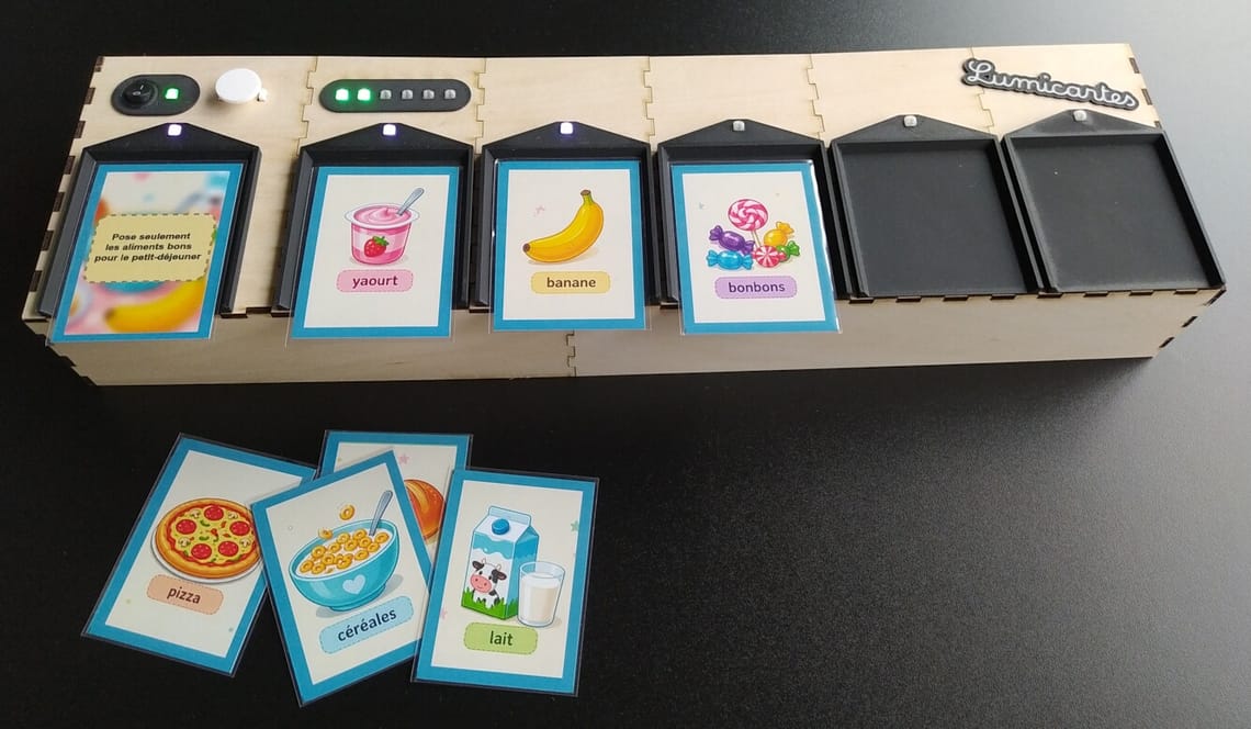
Lumicartes is an electronic game where the player has to answer questions using playing cards. It is one of the projects the LMDDC built for their « Speed dating with things » event. This is how to play :
- Take a set of cards
- Select and place a question card on the device at the first slot
- Select and place the answer cards on the other slots
- Press the action button to check if it is right
- The device will light a LED for each card that is correctly placed
- You can move the cards and press the button again until the answer is correct
- Once the answer is correct you’ll be rewarded by a colourful animation
- Restart with another question card
What were the requirements?
For our « Speed dating with things » event we wanted to showcase « things » that can be useful in an educational environment. We were focusing on things people can manipulate and that have no screens. This is how we get the idea of a game where you have to place cards and a device that will check the answers. At the end we made a device that is totally standalone, you don’t need any computer or phone to operate it, and you can even create your own set of cards by hands if you want. Then it can be used in pedagogical situations where pupils can create sets of cards for their classmates about topics learnt at school. The device is able to program the NFC tags of the cards, but you can also place cards in preprogrammed sleeves to make it easier.
Our goal was not to create a device that will be sold. The goal is to show people what is doable with widely available material (and a fair amount of manual labour). On top of that, it was a way for us to get familiar with our tools and see what can get out of our tiny workshop.
Our game is still a prototype, a proof of concept that can be used and tested in educative environment. We published all the data you need to build your own under an open-source licence : you can download it for free, modify it to your needs and even share your modifications. We pushed the openness a bit far because the proposed case is not even totally closed : we want people to see what’s inside the machine.
Sources are available here :
https://github.com/lmddc-lu/lumicartes
The main components
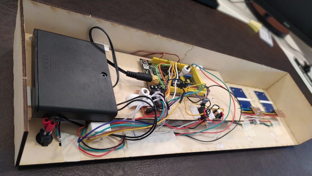
- An Arduino Mega 2560 compatible board : the brain of the device
- 6 RC522 modules : to read the RFID tags
- 1 Battery Holder Case
- 1 3v3 voltage regulator (800mA) for the RFID tags
- 10 1000R resistors and 10 2000R resistors
- 22AWG solid core copper wire
- 13 WS2812B individuals LEDs
- One or more perfboards (to cut as needed)
- A bunch of Ntag215 NFC Stickers and card sleeves
How it works
The device has 6 RFID/NFC sensors that read the RFID/NFC tags attached to the cards. Each answer card has a unique identifier written in their tag. In the question card tag we have this information :
- Type of card (0 for question)
- Type of question (ordered or not)
- The list of all the answer cards
This information is enough for the game to tell you if you are right or not. It is stored into the tags as key-value pairs encoded as a text string with dashes as delimiters.
Example of card contents:
French
T-1-D-42
English
T-1-D-1337
German
T-1-D-123456789
Luxembourgish
T-1-D-314159265
What are the official languages of Luxembourg ?
T-0-O-0-D-314159265000001337000000042
T-0 is for a question card, O-0 is for an unordered question and the D-xxx will be cut in chunks of 9 characters to get the list of answer cards.
Create some sets of cards
We have three special cards that we use to change the device’s mode. First place the « Design Answer » card on the device and press the action button. The fourth LED is blinking in red, you are now in the « Design Answer » mode. This mode is to initialize your cards with a random number : remove the special card and place blank cards on all the slots then press the button. A green LED over the slots will tell you that the cards are programmed, you can replace them with another set of blank cards and press the button again until all your cards are ready.
Imagine you want to create a set of cards with an ordered question. Place the « Design Ordered » card on the device and press the button. The first Led is blinking, remove the card.
Now, place the question card on the first slot and the right cards on the other slots in the right order. You don’t have to fill all the slots. Press the button : your question card is now programmed with the list of answer cards.
If you want to create a question card with an unordered set of answer cards, do exactly the same but using the « Design Unordered » card.
Empty all the slots and press the button to go back to the play mode (or restart the machine).
I would have preferred the card programming to be easier by avoiding the card initialization step. I could have decided to initialize the cards during the programming of a set of cards: if the card already has an ID I keep it, if it doesn't I write a random ID on it. The problem is that for some reason the sensor may misread the card - card not properly aligned, two cards that were stick together - then it could overwrite a card that already have an ID, and then all the set of cards that was already programmed with it would be wrong. I chose to favor the reliability and not to hide the initialization step from the user.
The story and design choices
Once we validated the global concept and a use in educational context, I was in charge of the development of the game both for the hardware and the software.
NFC sensors
Our though was that the NFC technology was the best suited to our needs because it is relatively cheap and low-tech. But I never used it in a project, so I was already left with some questions :
- Which NFC modules to use ?
- Which tags are compatible ?
- At which distance can we read a NFC tag ?
- Will the NFC sensor or tags interfere with each other ?
It was hard to find answers online because most people don’t use multiple sensors at the same time. I had to do some tests and I started with some RC522 modules that a colleague gave me.
I connected a module to an Arduino Mega and started to play with it. First win : I was able to write some texts on tags and to read it back.
Then, is it possible to read multiple tags at the same time ? The Internet told me it was a bad idea, but I made a prototype on a breadboard with up to 4 sensors anyway. It quickly became a wiring nightmare.
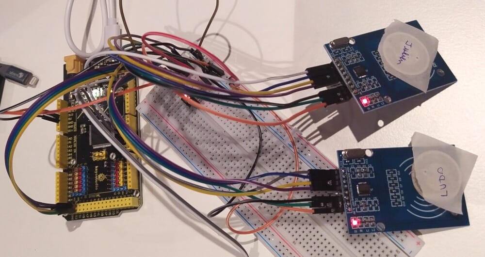
On the software side I had some hard time getting it to work, but finally it was working. The modules are using the SPI interface : they are connected in parallel and all use the same wires to talk with the Arduino. So we have to activate one NFC module at a time, check if a card is placed and readable, read it, parse its content, close the connection, maybe wait a bit and move on to the next module.
To test with more sensors I decided to start a more definitive assembly, soldering wires on the sensors. I got some intermittent bugs. Maybe it is a wiring issue or a bad sensor ? I spotted a problem with one sensor, I had to cut the wires and redo the wiring. Still got some bugs. Maybe it is a power issue now?
The RC522 modules are made for 3.3V but the Arduino board operates at 5V. A lot of people use it directly on 5V for small projects, but we know that it is bad. I added a 3.3V regulator on the assembly to power the sensors (the 3.3V power output of the Arduino board is too weak). The signals coming from the Arduino had to be converted to 3.3V too, I used some resistors to make a voltage divider.
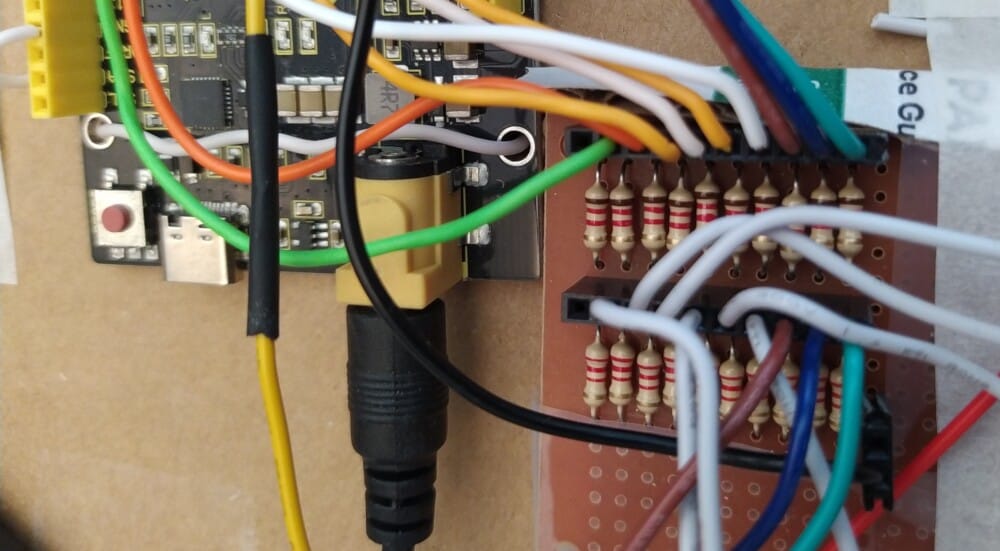
At the beginning I was supposed to use 8 sensors. Because of the reliability issues we decided to reduce the number of sensors to 6. It is still enough for the game to be playable (I personally think that it is even better like that).
Debugging hardware issues is hard. The worst is when sometimes it works and sometimes it didn’t, when you don’t have a strong failure you can reproduce.
When everything is wired together you cannot tell where the issue is coming from, this is why I finally redid the sensor wiring using header connectors. Disconnecting all but one sensor at a time and with the help of a voltmeter, I found a bad soldering on one sensor and on the voltage divider. For this last bug, I don’t understand how it could have even worked…
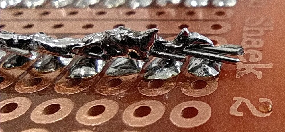
WS2812B LEDs and LED matrix
You win: the LEDs shows a colorful animation
The only indicators on the device are WS2812B LED modules. These are addressable RGB LEDs modules, that means that each module comes with its chip and a red, green and blue LED that can be individually controlled. These components are very common, I choose it because it was the easiest for wiring and programming : you just have to connect the 0V and 5V to all the modules and a data line to the first module. Each module have a data output that has to be connected to the next module data input. Then you just have to wire one data line to the Arduino and use a library to control the LEDs.
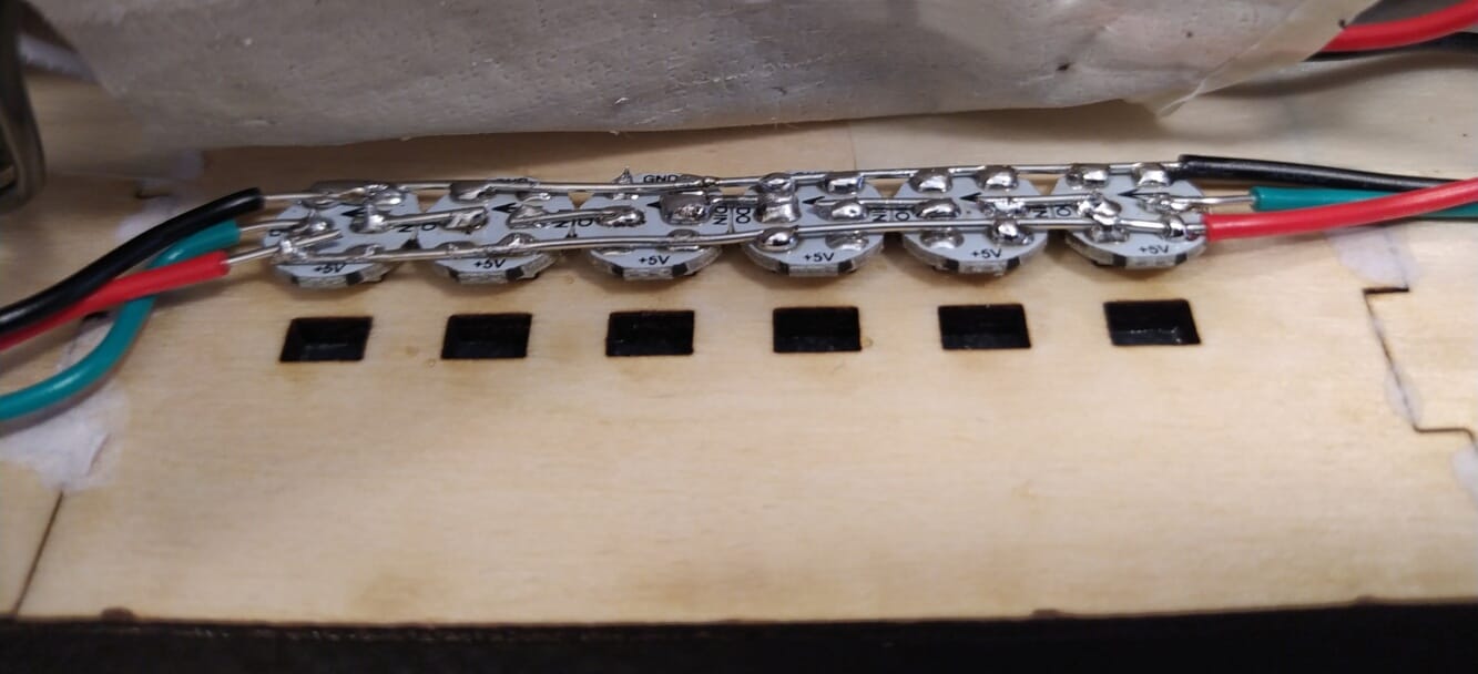
Before I added the addressable LEDs, I was using a LED matrix to get feedback from the Arduino board. My hope was to to use it in the final product, but I got weird bugs once I added the WS2812B LEDs to the breadboard so I removed it. In fact the screen was not important for the use of the device; less is more.
Arduino
Arduino is a well known brand of electronic boards. Their products are well suited for education and for prototyping. Their board schematics are open-source, this is why you can found a lot of cheap clones of their products. This made their designs a standard that is easily replaceable. And they provide an integrated development environment that is open-source too. For all these reasons the use of an Arduino board is a no-brainer for the LMDDC.
So, why the Mega 2560 board?
- We needed a lot of input-output
- The onboard 5V regulator is enough to power all the assembly
- Cheap enough
- A proven design
Power supply
I wanted to be able to recharge the device. I tought about using li-ion cells because they are very efficient, but they are a bit scary too. So the easiest way was to use a 6 AA battery holder with a jack barrel that can be plugged directly into the Arduino board. We use rechargeable NiMH batteries that are rated at 1.2V for a total of 7.2V once packed together, just enough to power the board. It is still compatible with alkaline cells (1.5V) if needed, and we can even plug a 9V power supply to the board.
The wires
At first, you could think that choosing the perfect wires is not that important, but you would probably change your mind once you start the wiring. Because the wires we need are relatively short and the components don’t draw that much current, we could use almost any cable (nevertheless, I still checked).
At the beginning I wanted to use multi-strand flexible wires. It happened that it was too easy to make short-circuits because the strands didn’t stick together. After some research I chose the 22AWG tinned solid copper wire. These are its benefits :
- It can handle the current needed for the assembly
- Two wires could stand in one perfboard hole
- The tinned copper is easy to solder
- It can be easily bent
- It will hold its shape, we can do pretty wirings
- It fits in PCB headers and breadboards
The last point allows us not to solder everything to the Arduino and still have a reliable connection. Perfect for our proto !
The housing
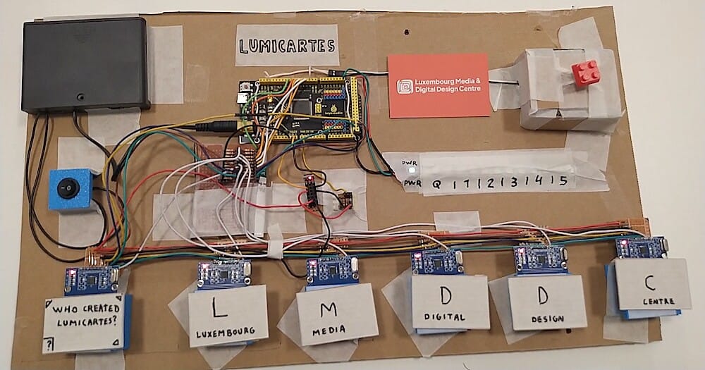
I started the prototype assembly on a big cardboard plate to move it around without destroying the wiring, but finally, it was time to think about a better assembly. It was hard for me to see how everything would fit in a box and still have room to place and connect everything together.
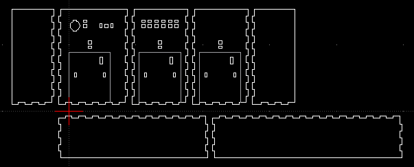
The external shape of the new box is made of laser-cut wooden plates glued together. The box is big enough to place the cards on it with the good spacing and with holes for the LEDs. I fastened the RFID readers and the LEDs inside the box, and then it was obvious that the solution was to place another plate on top with the Arduino and the batteries. I managed to clamp everything in a way that it is still possible to remove the parts.
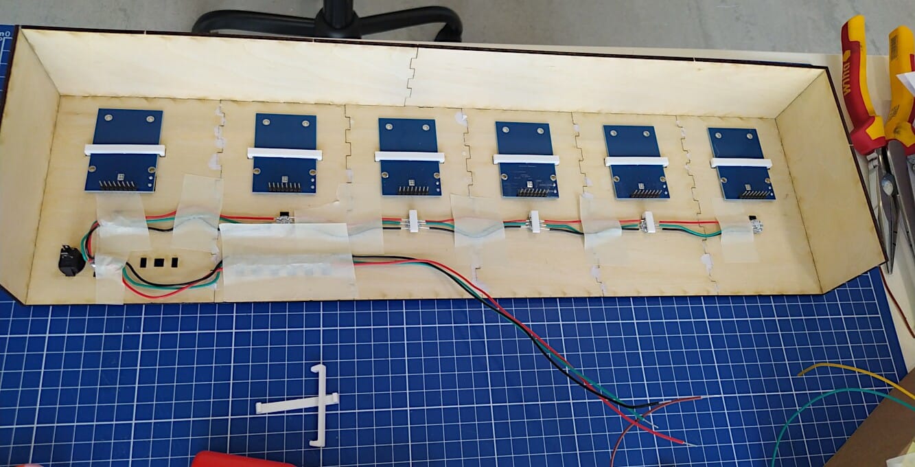
After that I continued to design and 3D print pieces to make it more polished (a button, card holders, transparent LED caps…).
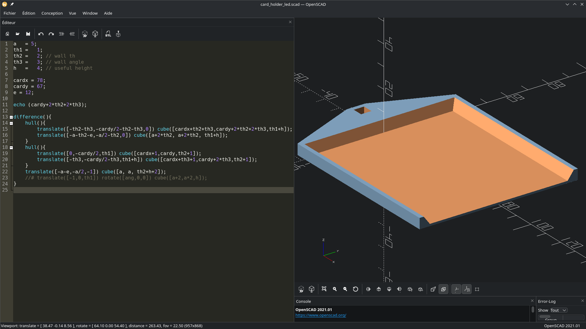
I designed the laser cutting drawings using LibreCAD and the 3D models using OpenSCAD. I don’t expect someone (or myself) to easily understand how to modify the SCAD files, they are mostly drafts. The game would deserve a totally new and better housing design.
The cards
I chose to use the more or less standard « poker » format, 88x63mm. People are used to handle it, there is enough room to put text on it, and it is easy to find sleeves for them.
I designed some cards with Inkscape, printed it, then I wanted to cut them with our plotter. It was my first try with it, my goal was to have a good quality cut with rounded corner. The cut itself was not bad, but it was hard to unstick the cards from the plate, and finally they were all twisted.
I then tried to cut the cards using the laser cutter, but the borders were getting covered with black ashes. Finally, I made a design to cut them with a paper cutter like in the good ol’ days. It was fast and clean. Goodbye the rounded corners, but we have a punch for that if we really miss it.
A word about the sleeves. The NFC tags are relatively cheap, but I don’t like wasting them on single-use cards. Then I stick the NFC tags on sleeves to be able to replace the cards if I want to. Another benefit is that you could let children create their own set of cards without having them to do the programming step. You just have to program the sleeves in advance, you can even put a clue inside the sleeve that will be hidden once the card inserted.
The software
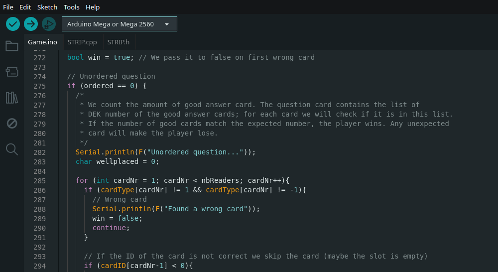
The Arduino has to be programmed in C/C++. Even if it is not my first Arduino project, I’m not that comfortable with these languages. My goal was to make a software that is easy to read, understand and modify, for myself and for newcomers. Then it is not perfectly optimised : not the perfect variable type for the contents, conversion of strings to numbers, numbers to strings, that may be avoided… But I think the result is decent and it achieves its goal.
Conclusion
As a tinkerer I really liked this project. It was cool to play with all our tools and transform our place in a tiny factory. The only downside is that until the end I was not one hundred percent sure not to find an unexpected bug or technical issue.
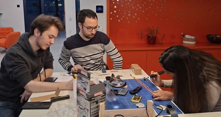
The story would not be complete if I don’t talk about my lovely colleagues that helped me for the soldering/desoldering steps, the design of the cards, their manufacturing and the testing. We all learned something and got new skills.

Ludovic Kiefer